Line? What a weird topic? Many models need lines, such as Turtle Spiral Generator and Symmetrical triangle generator. They are all based on lines.
Unfortunately, OpenSCAD lacks a built-in module named polyline. What should we do now?
The polygon module
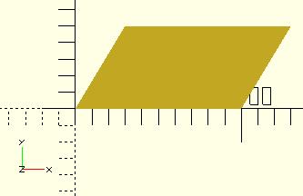
OpenSCAD has a built-in polygon module which accepts a list of [x, y] coordinates to create a multi-sided shape. The official documentation provides several simple examples. The polygon module also has a paths parameter which indicates the order to traverse the points.
polygon(points=[[0,0],[100,0],[130,50],[30,50]]);
 polygon([[0,0],[100,0],[130,50],[30,50]], paths=[[0,1,2,3]]);
 polygon([[0,0],[100,0],[130,50],[30,50]],[[3,2,1,0]]);
 polygon([[0,0],[100,0],[130,50],[30,50]],[[1,0,3,2]]);
The code fragments create the same parallelogram.

A line from two points
Why do you have to know the polygon module? After all, it's for creating a multi-sided shape, not for creating a line, right? Well, let's back to the topic. If you have to define a polyline module which accepts a list of points and connects all of them automatically, what do you have to solve first?
Divide and conquer is an essential skill of programming. The minimum task of the above requirement is connecting two points to form a line.
Maybe the first thought which comes to your mind is that OpenSCAD has a built-in square module. If it has two relatively short sides, the square looks like a line. Next, calculate the length between two points, the angle between the line and x-axis, rotate the line and move it to the right position and so on. Wow, it's troublesome.
Here is the second thought. OpenSCAD has a built-in polygon module. It accepts a list of [x, y] coordinates to create a multiple sided shape. Can we give it four points, which the last two points are calculated from the previous two points and the line width, to form a line? According to the thought, we implement a prototype below.
module line(p1, p2, width) {
    polygon([
        p1, p2, [p2[0], p2[1] - width], [p1[0], p1[1] - width]
    ]);
}

line([1, 2], [-5, -4], 1);
It seems pretty good.
Here, the last two points directly come from moving the previous two points vertically. If you are picky, you might say this is wrong. I cannot just move the two points vertically. It should be the distance between two parallel lines.
Well, I am also picky so let's be picky thoroughly. I want a line like this.
That is, the line is aligned center. According to the figure, we can derive a formula.
angle = atan((p2[1] - p1[1]) / (p2[0] - p1[0]));
Then, the four points passed into polygon is …
offset_x = 0.5 * width * cos(90 - angle);
offset_y = 0.5 * width * sin(90 - angle);
offset1 = [-offset_x, offset_y];
offset2 = [offset_x, -offset_y];
points=[
    point1 + offset1, point2 + offset1,
    point2 + offset2, point1 + offset2
];
Let's refactor the above code and define a module for it.
module line(point1, point2, width = 1) {
    angle = 90 - atan((point2[1] - point1[1]) / (point2[0] - point1[0]));
    offset_x = 0.5 * width * cos(angle);
    offset_y = 0.5 * width * sin(angle);

    offset1 = [-offset_x, offset_y];
    offset2 = [offset_x, -offset_y];

    polygon(points=[
        point1 + offset1, point2 + offset1,
        point2 + offset2, point1 + offset2
    ]);
}

line([1, 2], [-5, -4], 1);
We have a line now.
polyline
Once a line module which can draw a line from two points is ready, we can implement a polyline module based on it. You just take two points and draw a line sequentially until consuming all points.
module line(point1, point2, width = 1) {
    angle = 90 - atan((point2[1] - point1[1]) / (point2[0] - point1[0]));
    offset_x = 0.5 * width * cos(angle);
    offset_y = 0.5 * width * sin(angle);

    offset1 = [-offset_x, offset_y];
    offset2 = [offset_x, -offset_y];

    polygon(points=[
        point1 + offset1, point2 + offset1,
        point2 + offset2, point1 + offset2
    ]);
}

module polyline(points, width = 1) {
    module polyline_inner(points, index) {
        if(index < len(points)) {
            line(points[index - 1], points[index], width);
            polyline_inner(points, index + 1);
        }
    }

    polyline_inner(points, 1);
}

polyline([[1, 2], [-5, -4], [-5, 3], [5, 5]], 1);
The code creates a model like this.
Hmm? What are those gaps? The reason is the line module generates a square. One simple solution is adding a small circle at the point.
module line(point1, point2, width = 1, cap_round = true) {
    angle = 90 - atan((point2[1] - point1[1]) / (point2[0] - point1[0]));
    offset_x = 0.5 * width * cos(angle);
    offset_y = 0.5 * width * sin(angle);

    offset1 = [-offset_x, offset_y];
    offset2 = [offset_x, -offset_y];

    if(cap_round) {
        translate(point1) circle(d = width, $fn = 24);
        translate(point2) circle(d = width, $fn = 24);
    }

    polygon(points=[
        point1 + offset1, point2 + offset1,
        point2 + offset2, point1 + offset2
    ]);
}

module polyline(points, width = 1) {
    module polyline_inner(points, index) {
        if(index < len(points)) {
            line(points[index - 1], points[index], width);
            polyline_inner(points, index + 1);
        }
    }

    polyline_inner(points, 1);
}

polyline([[1, 2], [-5, -4], [-5, 3], [5, 5]], 1);
Finally, we get a polyline.
How about this polyline? It's just a simple implementation. There are still other implementations. For example, Archimedean spiral generator uses a different idea to implement a line. I'll talk about it in the later document. Try to come up with other ideas by yourself. It's also a joy when modeling by programming.

